 |
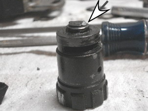
Figure 4. You will be working
with two locksets: the original broken one (A) with original
key cylinder and the replacement working one (B) with non-original
key cylinder. The whole lock assembly is held together by a lock
pin (arrow). Set the lockset in a soft vise and use a 1/16"
or 2-mm flat punch to drive the pin down and out. |
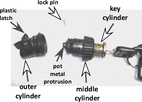 |
Figure 5. Once the lock pin is
driven through, the whole mechanism disassembles in three parts:
the outer cylinder holding the plastic latch, the middle cylinder
with the pot metal protrusion, and the key cylinder with pins
and springs.
BE CAREFUL when pulling the key cylinder of A out as the
pins and springs may tumble all over the place. No big deal for
B, as you won't likely have the key for that cylinder.
Carefully pull the key cylinder of A out by wrapping your fingers
on both sides of the cylinder over the pins. Insert it into the
new middle cylinder of B, which has the intact pot metal protrusion. |
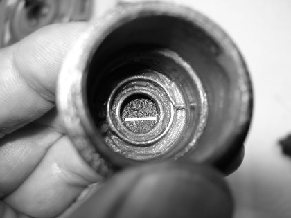 |
Figure 6. Now insert the new middle
cylinder into the outer cylinder (photo at left) by depressing
the plastic latch of the outer cylinder and inserting the new
middle cylinder (with original key cylinder inside) such that
the pot metal protrusion catches the lip (white line in photo)
of the plastic latch. [The circular spring is best set per Figure
7, rather than as shown here.] |
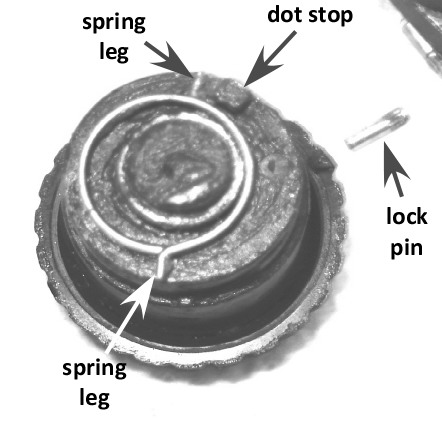 |
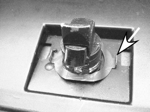
Figure 7. The knob on the glove box lock has a torsional spring
action, readily apparent when you twirled the knob before disassembly.
The best way to capture this spring action is to put the circular
spring on the end of the middle cylinder, as shown here, with
one spring leg that will catch on the small dot stop (arrow).
Gently insert the middle cylinder (with key cylinder kept intact
inside it) into outer cylinder and rotate the middle cylinder
so that other leg of circular spring catches on dot stop at bottom
of outer cylinder. Turn knob and check for spring tension. If
none is there, pull middle cylinder out partway and re-insert
it and try again to catch that dot stop with the spring leg.
It may take several tries. |
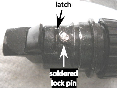 |
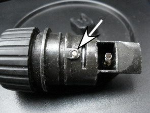
Figure 8. Once you have all the
cylinders together, check to see that the knob turns and that
it has tension. Next, use your key and see if it raises and lowers
the latch to lock and unlock the knob. When all these check out,
put whole lock into a soft vise and gently tap the lock pin (striated,
flared end first) into the hole. More than likely, the lock pin
will be slightly loose. To ensure it stays put, solder the top
with nonelectrical solder. File off excess solder.
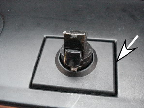
You're done! Install lock into glove box per reverse procedures
of Figures 2 and 3. |